Why are automatic drawing sheet links missing?
Answer
When you upload drawings into Procore, each image is processed with advanced image processing techniques (see Automatic Drawing Sheet Linking). These techniques first analyze a drawing and then automatically creates drawing sheet links for section cut callouts, which are used to reference other drawing sheets.
Important
For best results, Procore recommends uploading vector drawing files. Vector files should be unflattened and not scanned (as opposed to uploading a raster file). See What is the difference between raster and vector content in PDFs?Why upload a vector file?
- If a drawing is recognized as vector, then Procore will be able to read the vector text more reliably. For example, Procore might confuse an ’S’ for a ‘5’ in a raster file.
- Procore can find any Drawing Number in a vector callout as long as it is vector text, inside or outside of a circle callout symbol. If you upload a raster file, Procore will only be able to find section cuts, details and elevation callouts if they appear as a circle symbol with a Drawing Number inside.
Important notes for AutoCAD users
The following are the main things look for in order to create selectable and searchable text in a PDF from AutoCAD:
- Use a TrueType font.
- Do not alter the text from the original font, such as changing width (must be 1.0) or other style options.
- Make sure the Z coordinate value of the text is zero
AutoCAD users should turn off the "text as comments" feature before publishing a PDF for use in Procore. Exporting your drawings as a PDF with this feature enabled may impact Procore Drawings tool OCR.
- To do so, navigate to the command line in AutoCAD. Enter EPDFSHX and change the value to zero (0).
Troubleshooting common issues
Ideally, drawing sheet links are properly added to every callout in your uploaded drawings. However, in order to prevent against accidentally creating incorrect sheet links for "false positives" we've purposely set the threshold for the image processing algorithm to give us the most sheet links without creating any incorrect links.
If you notice that drawing sheet links are not being added to some or all of your drawings or you are seeing inconsistent results where some section cuts are not properly sheet linked like other ones, you should inspect your drawings to determine what might be causing the links to not be drawn as expected.
Several of the most common reasons why the Automatic Drawing Sheet Linking feature cannot add drawing sheet links to your uploaded drawings are highlighted below.
- A drawing with the same exact Number must exist in the drawing log in order for a hyperlink to be created that points to it. Make sure the drawing number exists in your Drawings tool.
- Drawings in different drawing areas will not link to each other. (e.g. Drawing A-601 in Area 1 will not link to drawing A-602 in Area 2.)
- Drawings will not link to themselves. (e.g. Drawing A-601 will not link to A-601).
- Procore will not link one or two digit drawing numbers. For example, an alphanumeric drawing number of A-1 would be recognized, while a numeric drawing number of 55 would not.
- Procore recommends that you embed fonts in your PDF files when saving them so that they display as expected when opened in other programs.
- Section cuts are not recognizable on the sheet. See the following considerations.
- Graphical Interference
- If a section cut is on top of a design element in the drawing (e.g. line, shape, shade, etc.)
.png?revision=1&size=bestfit&width=84&height=93)
- If the drawing numbers bleed over the edge.
.png?revision=1)
- If the drawing has low resolution that resulted in broken or blurry lines.
.png?revision=1)
- If the callout does not have a circle around it.

- If a section cut is on top of a design element in the drawing (e.g. line, shape, shade, etc.)
- Odd Fonts
- If your drawings have a hard-to-read font
.png?revision=1&size=bestfit&width=91&height=95)
- If your drawings have a hard-to-read font
- Non-equivalent Drawing Numbers
- If the drawing number listed on the drawing sheet is longer than or not equivalent to the drawing number within the callout, Procore will not recognize the two drawings as being the same.
- E.g. British Standard Drawing Number Format
- Drawing number listed on the title block: DD_AR_PJW_G_101_0
- Drawing number listed in the callout: G101
- E.g. British Standard Drawing Number Format
- If the drawing number listed on the drawing sheet is longer than or not equivalent to the drawing number within the callout, Procore will not recognize the two drawings as being the same.
- AutoCAD Formatting
- AutoCAD users should turn off the "text as comments" feature before publishing a PDF for use in Procore. Exporting your drawings as a PDF with this feature enabled may impact Procore Drawings tool OCR.

- To do so, navigate to the command line in AutoCAD. Enter EPDFSHX and change the value to zero (0).
- AutoCAD users should turn off the "text as comments" feature before publishing a PDF for use in Procore. Exporting your drawings as a PDF with this feature enabled may impact Procore Drawings tool OCR.
- Text Saved as Lines, not Text
- If the lettering in the callout wasn't saved as Text, but lines, the Vector OCR will rely on Raster detection and the callouts will not be detected.
- This can happen if the font used in AutoCAD doesn't translate to the PDF as Text and instead translates to the same line type as the walls and tables on the drawing. There are two types of fonts available in AutoCAD: SHX and TrueType.
- Only the TrueType fonts get saved as text when the PDF is created.
- SHX fonts are saved as lines.
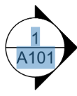
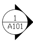
- The easiest way to tell if they were saved as lines or text is to see if you can highlight the text in a PDF reader such as Adobe Acrobat or Bluebeam, as shown in the screenshots below:
- If the lettering was saved as text, you will be able to highlight the text, and the callouts will be detected.

- If the lettering was saved as lines, you will not be able to highlight the text, and the callouts will not be detected.

- If the lettering was saved as text, you will be able to highlight the text, and the callouts will be detected.
- In order to get the callouts to be automatically linked, you will need to have the drawing changed to use a TrueType font in the callouts and then upload the drawing again.
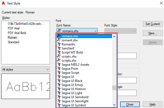
- To check what type of font was used in AutoCAD, open Text Style as shown in the screenshot below.
- TrueType font are indicated by the the "TT" icon next to the name
- SHX fonts end with .shx.

- To check what type of font was used in AutoCAD, open Text Style as shown in the screenshot below.
- This can happen if the font used in AutoCAD doesn't translate to the PDF as Text and instead translates to the same line type as the walls and tables on the drawing. There are two types of fonts available in AutoCAD: SHX and TrueType.
- If the lettering in the callout wasn't saved as Text, but lines, the Vector OCR will rely on Raster detection and the callouts will not be detected.
- Graphical Interference
Next Steps
- To resolve this issue without editing the drawing itself, simply Add a Link to a Drawing manually.